Introduction to SMT Soldering in PCB
SMT soldering involves mounting electronic components directly onto the surface of a printed circuit board (PCB). This method is preferred for its efficiency, compactness, and reliability in producing high-quality electronic devices. Surface Mount Technology (SMT) soldering is a crucial technique in modern electronics manufacturing in Printed Circuit board

Parts of SMT Soldering
PCB Cleaning:
Ensure the PCB is clean and free of contaminants. Use isopropyl alcohol and a lint-free cloth to wipe down the board.
Component Check:
Verify that all components are in good condition and match the specifications for your project. This includes checking for correct part numbers and values.
Solder Paste Application
Stencil Usage:
Place a stencil over the PCB to align with the pads where the components will be mounted. The stencil ensures that solder paste is applied precisely.
Solder Paste Application:
Use a squeegee or spatula to spread the solder paste over the stencil. Ensure even coverage across all the pads.
Stencil Removal:
Carefully lift the stencil off the PCB, leaving the solder paste only on the designated pads.
Component Placement
Pick-and-Place Machine:
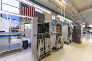
If available, use a pick-and-place machine to automatically place components onto the printed circuit board PCB. This method ensures accuracy and speeds up the assembly process.
Manual Placement:
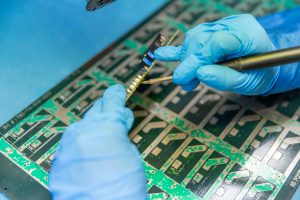
For small projects or prototypes, manually place the components onto the pads with tweezers or a vacuum tool. Ensure each component is correctly oriented according to its polarity and design specifications.
Reflow Soldering
Preheating:
Preheat the PCB in a reflow oven or hot air rework station. This helps to activate the flux in the solder paste and prepares the board for soldering.
Reflow Process:
Gradually increase the temperature to melt the solder paste. The components will bond to the PCB as the solder flows and solidifies. Follow the recommended temperature profile for your specific solder paste to achieve optimal results.
Cooling:
Allow the PCB to cool gradually to prevent thermal shock and ensure strong solder joints.
Inspection and Testing
Visual Inspection:
Examine the solder joints under a magnifying glass or microscope to check for defects such as bridging, insufficient solder, or cold joints.
Automated Optical Inspection (AOI):
Use an AOI machine to automatically inspect the PCB for any soldering defects.
Electrical Testing:
Perform electrical tests to verify that the circuit functions correctly. This can include continuity tests, voltage measurements, and functional testing of the assembled device.
Rework and Repair
Identifying Issues:
Identify any issues found during inspection or testing and mark the affected areas on the PCB.
Desoldering:
Use a soldering iron, desoldering pump, or hot air rework station to remove faulty components or excess solder.
Re-soldering:
Apply fresh solder paste and replace the component, then reflow the solder joint to achieve a secure bond.
Conclusion
SMT soldering is a multi-step process that requires precision and attention to detail. By following these steps, you can ensure reliable and high-quality solder joints for your electronic projects. For further guidance or professional assistance, don’t hesitate to reach out to our experts sales team

