

Admin, November 15,2021
What Is The Electro-Mechanical / Box Build Assembly Process?
Altest has always focused on providing a solution in-house to any PCBA challenges that our clients may face. Clients in the past have tasked Altest with fully taking their project from a prototype to a market-ready product through a process known as a box-build assembly. A box-build assembly is taking the initial finished PCB after it has been assembled and manufacturing an enclosure with things such as testing, packaging, software installation, etc done by the manufacturer. This eliminates the complexity of warehousing, shipping, and other complications with creating a final product for start-ups or smaller companies without an established infrastructure. Each step involved in a box-build assembly process increases in complexity depending on how fleshed out the client wants their final product to be. It is beneficial for the client and the manufacturer if there are included CAD models and packaging design already designed to expedite the manufacturing process.

Box-Build Exploded View
The first step in the manufacturing process for a box-build project is assembling the PCB with the client’s design that accounts for the design of the final enclosure. You can find a more detailed explanation about the PCB assembly process and each step in manufacturing here. It begins with submitting a GERBER file of the PCB board as well as a BOM otherwise known as a bill of materials which will be used to quote a client’s project. Once a BOM has been approved and a price for the build is approved and submitted the manufacturer begins the process of procurement. It’s common for clients to provide some parts they may have already had on hand as well as blank PCBs as consignment parts. Altest offers the ability to procure components from our 100,000+ line item warehouse as well as our PCB fabrication partners to expedite the procurement stage of manufacturing.
Once the parts are all acquired the manufacturer can start kitting the build for the production floor to ensure that every component is accounted for. This ensures that no component is lost during manufacturing to ensure that there will be no delays due to a missing component. The blank boards go through the process of component assembly including SMT process assembly and through-hole assembly. Most box-builds require the installation of connectors such as display ports and USB ports which uses the through-hole mounted assembly process (learn more here).
Everything starts by submitting a quote using our free quote tool here.
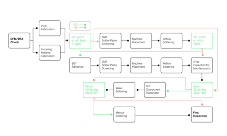
Manufacturing Flow Chart
Once the PCB is completed and tested for any flaws then the board can be moved onto the next step which is software installation. A client should provide the necessary tools to install the board’s software which our engineering teams can learn and continue to apply to each board. This eliminates the need for the finished board to bounce between customers and manufacturers. A software installation guide is recommended with troubleshooting to ensure that there are no delays during this step to ensure rapid delivery and customer standards.
Print Circuit Board Flash Programming
A client creates what they want as a final product which includes the PCB GERBER file, Bill-of-Materials, and enclosure CAD drawings. CAD drawings should specify the exact product measurements of the enclosure. Once a CAD drawing is finalized and materials selected we work with our plastic and metal manufacturing partners to create an affordable enclosure that meets the needs of the clients.
CAD drawings should have detailed information on the product enclosure such as dimensions, sizes, relations, aspects, properties, and characteristics of the enclosure to ensure an accurate final product. Some companies struggle with this stage, but Altest offers a highly skilled team of engineers to assist in the CAD drawing creation should the need arise.
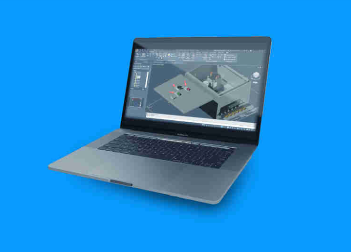
CAD Design Software
The CAD drawings provided by the client will then be sent over to our manufacturing teams to start enclosure production to finish concurrently with the PCB boards. Our manufacturing teams are well versed in plastic and metal enclosure manufacturing with multiple finishing options such as powder coating or anodized. Once the enclosures are finished being manufactured they’ll have any labels or custom graphics applied onto them such as warranty stickers or logos. Once the boards are completed and the enclosures are ready then the boards must go through PCBA integration.
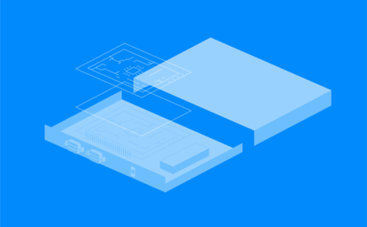
Box-Build PCB Enclosure
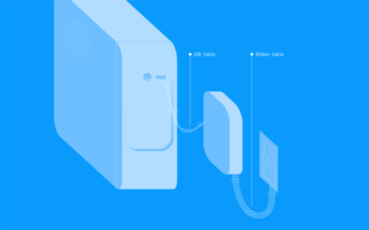
Cables and harnesses must be planned out with wire diagrams from the client to ensure easy access for servicing, testing, and compliance. Altest offers a dedicated cable/harness engineering team and is able to manufacture custom harnesses as well as expertly assemble them.
There are mainly 2 types of wires: Solid (single conductor) and Stranded (Multiple conductors).
Solid conductor wire is constructed of one single core of the wire, whereas stranded wire is multiple strands of wire grouped together to make up the single core. Solid wires are more rigid and more durable which are commonly used in building wiring. Stranded wires are more flexible and more commonly used in robotic applications. Other cable varieties include coaxial, ribbon, shielded, twisted pair, and fiber optic cables. The AWG (American Wire Gauge) standard is used to identify the width of the wire, from very thin (0.003 inches) to 3 or more inches in thickness.
Another key factor is the airflow of the enclosure which is a key factor when a pneumatic assembly process to avoid any kinks or bends.
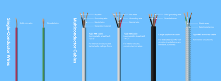
Cable Types used in Box Build Assembly
Pneumatic systems make use of pressured gas to actuate a device to function. They are generally powered by pressurized air or inert gases. A small or large-scale compressor is needed to power up cylinders, motors, and other pneumatic devices. Pneumatic systems are commonly used in medical, packaging, material handling, entertainment, and robotic applications. These systems are sometimes preferred because they are inexpensive, versatile, reliable, and less dangerous than electronic actuators, electric motors, and solenoids.
They can be especially helpful in hazardous conditions such as in mining operations as a stray spark could cause a reaction in certain environments. Pneumatic systems can be used in combination with various other electrical/electronic integrated systems to activate certain parts of a device. They are particularly useful where minute loads are desired.
Pneumatic systems are commonly seen in everyday items such as air brakes, nail guns, air hammers, and vacuum pumps. Sophisticated electronics are used to accurately control airflow in many robotic applications.
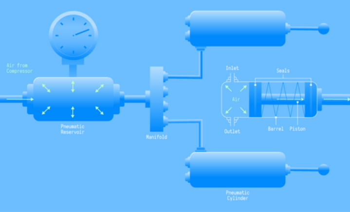
Pneumatic System
During the manufacturing, stage labels are added to the enclosure and boards beforehand to allow for our tracking system to manage each board in case of failure or loss which is standard for Altest regardless of a box-build. Each board can easily be tracked for RMA in case of failure and a warranty can be given to the final end-user determined by the client.
Altest has experience in packaging engineering as well as shipping logistics. We can also use any specified shipping procedures determined by the client as well such as custom packaging, labeling, and materials for purposes such as marketing. Altest has established shipping partnerships and can handle shipping logistics for the client to ensure that it reaches the end-user quickly and affordably.
Altest has a full-sized component warehouse with space to store and warehouse any box-build assembly product. Our warehouse has built-in climate control, humidity monitors, traceability software and full security to ensure the safety of a client’s product.
Packaging
Share: