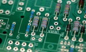
Through-Hole Assembly (also known as Through-Hole Technology or THT) is a type of electronic assembly process in which components with leads (or pins) are inserted into holes drilled through a printed circuit board (PCB) and soldered on the opposite side. This is one of the traditional methods of mounting electronic components and is particularly well-suited for components that require a more robust mechanical connection, or for applications that involve heavy-duty components, power devices, or high-stress environments.
While Surface-Mount Technology (SMT) has largely replaced through-hole in modern electronics, through-hole assembly is still essential in many industries where component reliability, thermal performance, or the need for higher mechanical strength is critical.
Through-hole assembly is a multi-step process that includes component insertion, soldering, inspection, and testing. Here’s an overview of each step in the process:
Before the components can be inserted into the PCB, the PCB itself must be prepared.
Once the PCB is prepared, the next step is inserting the components. Through-hole components have leads that go through the holes in the PCB.
In small-scale or low-volume production, manual insertion may be used. Workers manually insert each component through the correct hole in the PCB, bending the leads on the opposite side to hold the components in place.
After insertion, the component leads may need to be bent or trimmed. Lead bending machines are used for this step, particularly in automated environments, to ensure the leads are in the right position for soldering.
Once the components are inserted and the leads are secured, the next step is soldering. There are two main methods for soldering through-hole components: wave soldering and hand soldering.
For mixed-technology boards (combining both through-hole and surface-mount components), selective soldering is used. This method involves using a soldering iron or a robotic arm to selectively apply solder only to the through-hole component leads, avoiding the surface-mount areas.
After soldering, the PCB undergoes additional steps to ensure the assembly is clean, functional, and free from defects.
After the soldering process, thorough functional testing is performed to ensure the board operates correctly. This step includes:
After testing, the PCB undergoes a final inspection to ensure it meets quality standards.
A final visual inspection ensures all components are properly inserted and soldered, and that there are no visible defects like misaligned components, solder bridges, or mechanical damage.
System Integration and Box Build Assembly refers to the process of assembling and integrating complex electronic systems within a protective enclosure or box. This includes not only assembling the electronic components onto a printed circuit board (PCB), but also incorporating those PCBs into a larger system, connecting various subsystems (such as power supplies, connectors, sensors, switches, displays, etc.), and ensuring the final product is properly housed in a box or enclosure for protection, usability, and functionality.
Box build assembly typically involves the integration of hardware, software, and mechanical elements, creating a fully functional system or product. This process is crucial for industries like consumer electronics, automotive, industrial equipment, medical devices, telecommunications, and aerospace, where end products are often complex systems that require both electronic and mechanical assembly.
The system integration and box build assembly process generally includes several stages: Design and Engineering, Assembly of the Electronics, Mechanical Assembly, System Integration, Testing and Quality Assurance, and Final Packaging. Below is a detailed breakdown of each stage:
The first step in the box build process is to design the overall system architecture, including both the electronics and the mechanical aspects.
System Design and Requirements
Once the design is complete, the assembly of the electronic components begins. This step typically includes the SMT (Surface-Mount Technology) assembly of the PCB, followed by the integration of the PCB with the other system components.
PCB Assembly (SMT and Through-Hole Components)
This phase involves the assembly of the mechanical parts of the system, including the enclosure and any external components. This is often done in parallel with the electronic assembly.
This is the phase where all parts of the system come together. It involves both the electrical integration and the mechanical integration of the components.
If the system includes programmable components (e.g., microcontrollers, FPGAs), the firmware or software is loaded onto the devices, and the system is configured for its intended operation.
Comprehensive testing is crucial to ensure the system operates as intended. Testing verifies both the electrical performance of the system and its mechanical integrity.
The system may need to meet specific industry standards or regulatory requirements, such as CE, UL, or RoHS certifications, depending on the product type and target market.
Once the system has passed all tests and quality checks, it is ready for final packaging.
System integration box build assemblies are used in a wide variety of industries and applications, including:
Surface-Mount Technology (SMT) Assembly is the process of assembling electronic components directly onto the surface of a printed circuit board (PCB) without the need for through-holes. In SMT, the components are typically small and are mounted on the surface of the PCB using solder paste and reflow soldering. This process is highly automated, efficient, and suitable for high-volume manufacturing of compact and reliable electronic devices.
The SMT assembly process involves several stages: solder paste application, component placement, reflow soldering, and inspection and testing. Here’s an overview of each stage:
The first step in SMT assembly is the application of solder paste to the PCB. Solder paste is a mixture of small metal solder balls (usually made of tin, silver, and copper) suspended in a flux medium. The paste serves both to hold the components in place and to form the solder joints once heated.
Once the solder paste is applied, the next step is the placement of surface-mount components (SMDs) onto the PCB. Components can include resistors, capacitors, integrated circuits (ICs), connectors, and LEDs, all of which are small and designed to be mounted on the surface of the PCB.
Pick-and-Place Machines: These automated machines are used to pick up the components from reels or trays and place them onto the correct locations on the PCB.
Vacuum Grippers: The pick-and-place machine uses vacuum suction to pick up the components and place them accurately on the pads covered with solder paste.
Placement Accuracy: These machines are highly precise, capable of placing components with tolerances of a few mils (thousandths of an inch). This is essential for handling very fine-pitch components like BGAs (Ball Grid Arrays) or QFNs (Quad Flat No-leads).
Component Orientation: For polarized components (like diodes or electrolytic capacitors), the machine ensures they are oriented correctly according to the PCB design.
Component Size: SMT is ideal for small, lightweight components, typically ranging from 01005 (the smallest size) to components with large thermal dissipation like power transistors.
Placement Speed: High-speed pick-and-place machines are capable of placing thousands of components per hour, making the process efficient for high-volume production.
Precision: The placement accuracy is crucial for ensuring reliable solder joints and preventing defects such as misalignment or tombstoning (when a component stands upright due to uneven soldering).
After the components are placed, the PCB is passed through a reflow soldering oven, where the solder paste is melted to form solid solder joints between the PCB pads and the component leads.
Preheat Zone: The PCB is heated gradually in the preheat zone to avoid thermal shock and to activate the flux in the solder paste. This zone prepares the board for the reflow stage.
Reflow Zone: The PCB enters the reflow zone, where the temperature is raised to the melting point of the solder paste (typically around 220-250°C). This causes the solder to melt and form a bond between the component leads and the PCB pads.
Cooling Zone: After the solder is melted, the board is gradually cooled, allowing the solder to solidify and form reliable solder joints.
Temperature Profile: The reflow soldering process requires a carefully controlled temperature profile to ensure that the components and solder paste heat evenly. Too high a temperature can damage components, while too low a temperature may result in insufficient soldering.
Solder Joint Quality: Proper reflow soldering results in well-formed solder joints that are both mechanically strong and electrically conductive.
After reflow soldering, the assembled PCB is thoroughly inspected and tested to ensure that all components are correctly soldered and that the board functions as expected.
AOI is used to automatically check for defects in the solder joints, component placement, and alignment. It captures high-resolution images of the board and compares them to a predefined template to identify common issues like:
Solder bridges
Missing components
Misaligned components
Insufficient or excessive solder
Benefits: AOI is fast, non-destructive, and can detect issues that are invisible to the naked eye, such as micro-solder bridges or fine-pitch misalignments.
For more complex PCBs with hidden or non-visible solder joints (such as those under BGAs or QFNs), X-ray inspection is used to check the quality of the solder joints.
X-ray inspection helps to detect issues like:
Insufficient solder
Voids (air pockets) in the solder joint
Cold solder joints
BGA solder ball defects
Functional testing ensures that the finished PCB performs as expected in its intended application. This may involve:
Applying power and checking for correct voltages
Signal testing and functional checks (e.g., communication protocols, signal integrity)
Automated tests or manual tests (e.g., using oscilloscopes or multimeters) are performed to verify the PCB’s functionality.
After successful inspection and testing, the PCB undergoes a final quality check to ensure that all aspects of the assembly are correct.
If necessary, the PCB is cleaned to remove any flux residue left from the soldering process. Ultrasonic cleaning or brush cleaning with solvents may be used to ensure the board is free from contaminants.
The final PCB assemblies are carefully packaged to avoid damage during transport. Anti-static bags, trays, or tubes are often used to protect the boards from electrostatic discharge (ESD) and physical damage.
Higher Component Density: SMT allows for smaller components and higher component density, leading to more compact and lightweight PCBs.
Improved Reliability: SMT components tend to have better mechanical and thermal properties compared to through-hole components, leading to improved reliability.
Automated Process: SMT assembly is highly automated, allowing for high-speed production with minimal human intervention, which is ideal for mass production.
Lower Costs: The automated nature of SMT reduces labor costs and material waste, making it cost-effective for large production runs.
Flexibility: SMT can be used for both low and high-volume production and is suitable for a wide variety of component types (e.g., resistors, capacitors, ICs, LEDs).
SMT is widely used in the assembly of electronic products across many industries, including:
Consumer Electronics: Smartphones, laptops, tablets, TVs, and gaming consoles.
Automotive: Electronic control units (ECUs), infotainment systems, sensors, and power management systems.
Medical Devices: Diagnostic equipment, wearable devices, and imaging systems.
Industrial Equipment: PLCs (Programmable Logic Controllers), robotics, and industrial control systems.
Aerospace and Military: Avionics, communications systems, and radar.
cable harness assembly is a collection of electrical cables or wires bundled together and organized to transmit power or data within a device or machinery. This assembly is commonly used in various industries, including automotive, aerospace, consumer electronics, and industrial applications. The purpose of the cable harness is to provide a reliable, organized, and efficient way of routing and managing electrical signals or power between components.
Wires or Cables:These are the individual electrical conductors that carry power, signals, or data. They can be made of copper, aluminum, or other conductive materials, and may be insulated or uninsulated, depending on the application.
Connectors:These are used to attach the cable harness to other electrical components, such as sensors, controllers, motors, or power sources. Connectors may be pre-crimped to the wires or be attached during the assembly process.
Insulation or Sleeving: The cables may be covered with insulating materials (e.g., PVC, Teflon, or braided material) to protect them from environmental factors like heat, abrasion, and moisture.
Strain Relief:This is a mechanism used to prevent the cables from being pulled out of the connectors, reducing the risk of damage from physical stress.
Cable Ties or Clips: These are used to bundle the cables together in an organized way, often with a specific layout that minimizes tangling or interference.
Labels orMarkers:These are used to identify each wire or connector within the harness, which makes installation, troubleshooting, and maintenance easier.
Engineering & Planning: Before assembly, engineers design the cable harness according to the requirements of the application. This involves determining the wire types, lengths, connectors, and the layout to ensure that the harness will function properly within the system.
Bill of Materials (BOM):A list of all the components, including wires, connectors, terminals, and other materials needed for the harness.
Cutting and Stripping the Cables:The wires are cut to the required lengths and stripped of their insulation at the ends where connectors or terminals will be attached.
Crimping:The stripped ends of the wires are attached to connectors using crimping tools, which securely press the metal contacts of the connector onto the wire ends.
Soldering:In some cases, wires may be soldered to the connectors or terminals.
Bundling and Organizing:The wires are bundled together using cable ties, clips, or spiral wrap. The bundle may be arranged in a specific pattern to reduce electromagnetic interference (EMI) or to optimize space.
Insulation or Sleeving:Depending on the environmental requirements, the cables are sleeved with heat shrink tubing or other insulating materials. This provides extra protection from heat, abrasion, and chemicals.
Testing and Quality Control:Once the harness is fully assembled, it undergoes electrical testing to check for continuity, short circuits, and proper functionality.
Mechanical tests like pull tests and bend tests may also be conducted to ensure durability and strain resistance.
Final Inspection andPackaging:The harness is inspected to ensure that it meets design specifications and industry standards. It is then packaged for shipment or installation.
Automotive Industry:Cable harnesses are used to interconnect electrical systems within vehicles, such as the engine, lights, and infotainment systems.
Aerospace:They are used in aircraft for controlling various systems, including avionics, electrical power, and communications.
Consumer Electronics:Cable harnesses help organize internal wiring for devices like computers, televisions, and smartphones.
Industrial Machinery: In factories and production lines, cable harnesses provide power and data connections to motors, sensors, and control systems.
Reduced Installation Time: Pre-assembled cable harnesses simplify installation, reducing the need for complex wiring during assembly.
Organization:They keep electrical systems organized, preventing loose or tangled wires that could lead to errors or damage.
Space Efficiency:A well-designed cable harness minimizes the use of space and allows for efficient routing of wires.
Improved Durability:Properly designed and protected cable harnesses are more resistant to wear, vibration, and environmental factors, leading to a longer lifespan of the electrical system.