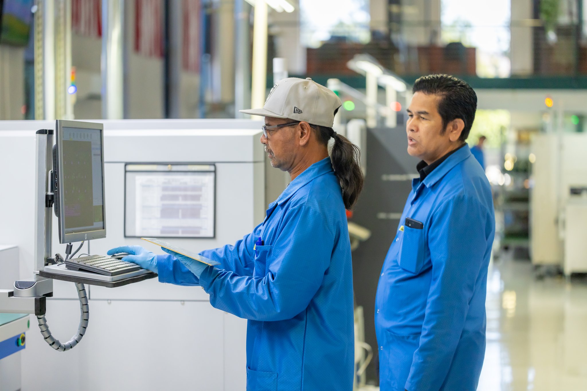

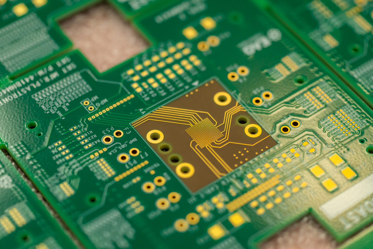
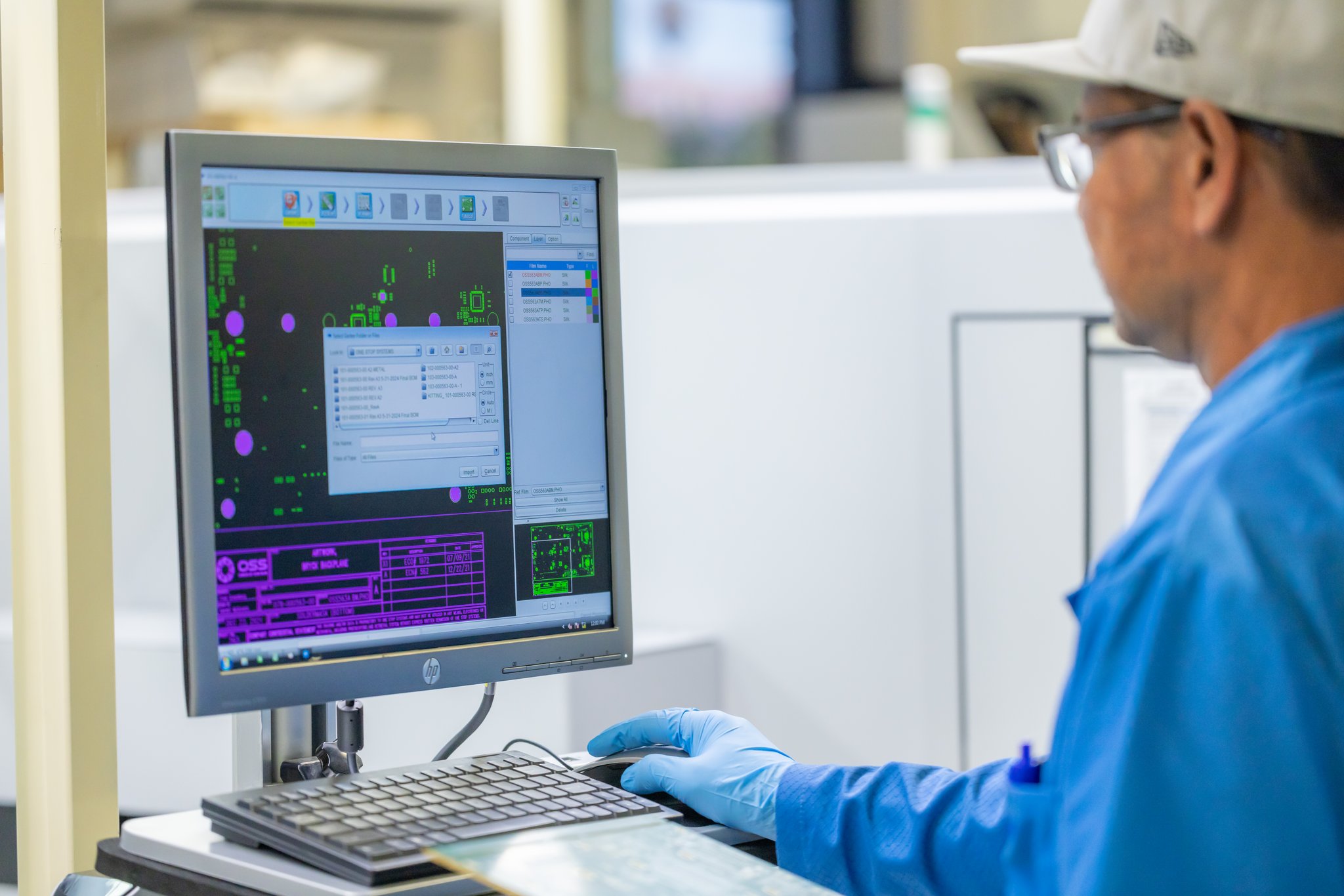
DFM (Design for Manufacturability) in PCB design is the process of optimizing a circuit board’s layout, dimensions, and tolerances to ensure it can be reliably and cost-effectively fabricated and assembled. It prevents manufacturing defects, lowers production costs, and speeds up time-to-market.
PCB design for manufacturability (DFM) involves optimizing a PCB layout, ensuring a smooth fabrication and assembly process. All problems associated with PCB design can be mitigated through proper DFM processes.
Incorporating DFM principles early in the design phase can provide significant benefits to companies, such as.
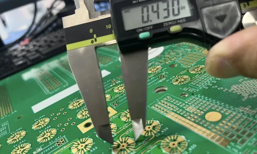
Cost Reduction: By designing products that are easier to manufacture, businesses can reduce production costs related to materials, labor, and machinery. DFM also minimizes the need for expensive changes or rework after production begins.
Improved Product Quality: DFM allows manufacturers to identify potential production challenges early on and address them in the design phase, leading to higher product quality.
Faster Time-To-Market: Assembly and installation take less time when DFM principles are followed. DFM reduces the need for manpower and eliminates the need for redesigns and iterations. With DFM processes, more products are able to be manufactured in a shorter span of time. Incorporating DFM aspects into PCB design provides alternative component choices, considering the availability of the original component selected. In this way, DFM processes decrease lead time and product time-to-market.
A Comprehensive Design for Manufacturing (DFM) Analysis is essential for ensuring your PCB design is optimized for reliable, efficient, and cost-effective production. Our engineering team conducts an in-depth review of every aspect of your design, including trace widths and spacing, drill sizes, pad geometry, annular rings, solder mask clearances, copper distribution, layer stack-up, component placement, thermal considerations, and manufacturing tolerances. By identifying potential production issues before fabrication begins, we help eliminate costly redesigns, reduce manufacturing defects, and improve overall production efficiency.
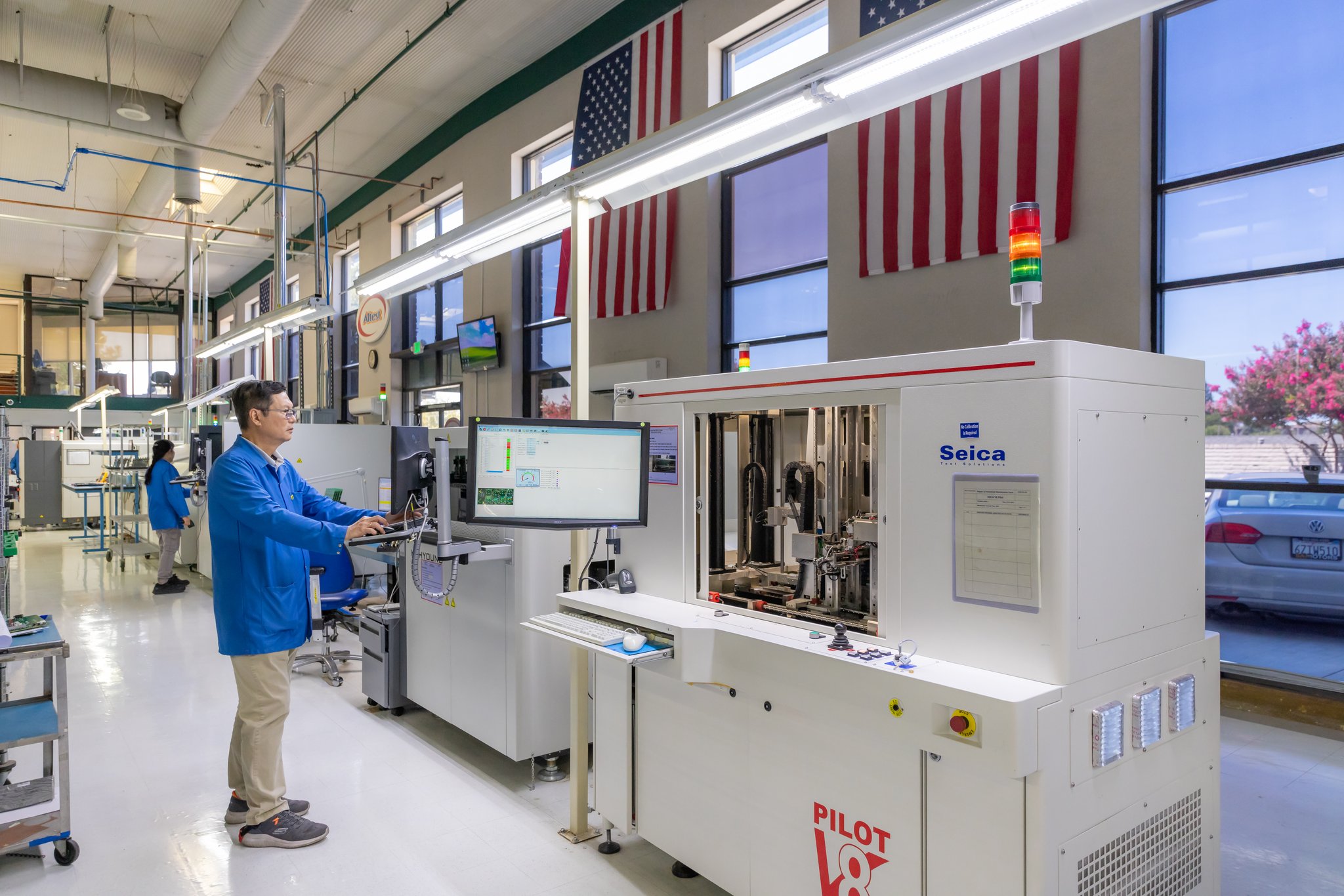
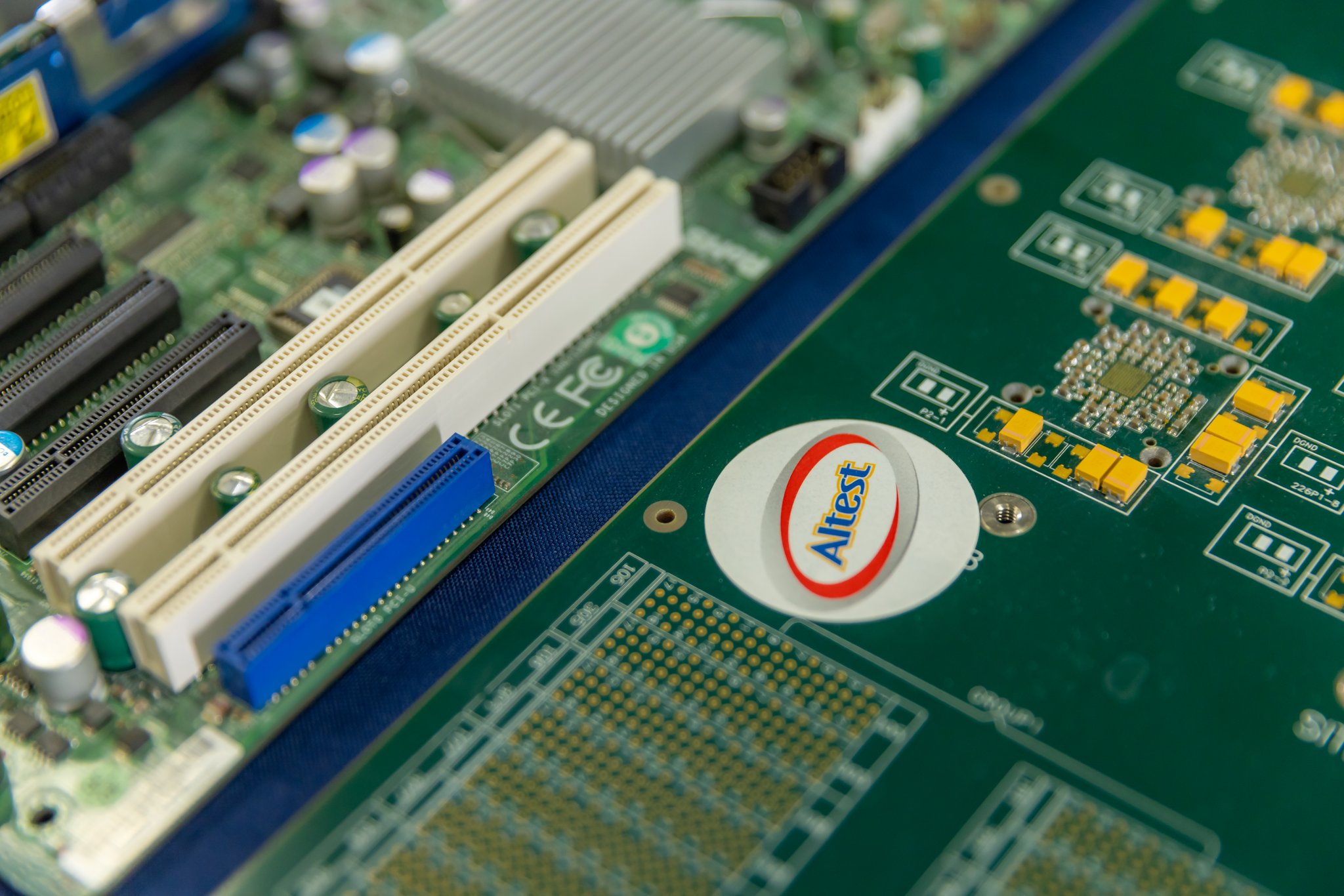
Design for Manufacturing (DFM) is a critical engineering process that ensures your printed circuit board (PCB) design is optimized for efficient, reliable, and cost-effective production. At every stage, our DFM experts analyze your design files to identify potential manufacturing issues such as trace spacing, pad sizes, drill tolerances, component placement, solder mask clearances, and layer stack-up. By addressing these challenges before fabrication begins, we reduce production risks, improve yield, minimize costly revisions, and accelerate time-to-market. Whether you're developing a prototype or preparing for high-volume manufacturing, our comprehensive DFM review ensures your PCB is built for maximum performance, reliability, and manufacturability.
Find answers to common questions about our DFM validation process, Valor NPI software, acid traps, annular rings, and cost-reduction strategies.
DFM is the engineering practice of designing a printed circuit board specifically to optimize its manufacturing process. It involves analyzing the CAD layout against the physical capabilities and tolerances of the fabrication and assembly equipment to ensure the board can be built reliably, efficiently, and at the lowest possible cost with maximum yield.
Finding a design flaw on a computer screen costs almost nothing to fix, but finding it on the factory floor can cost thousands of dollars in scrapped boards and delayed schedules. DFM catches critical errors—like acid traps, solder mask slivers, or starved thermals—before any physical material is cut or etched.
We utilize industry-leading DFM validation software, primarily Siemens Valor NPI. This powerful tool simulates the entire fabrication and assembly process, thoroughly analyzing the Gerber/ODB++ files against hundreds of specific manufacturing rules to catch potential yield-reducing defects that native CAD DRCs often miss.
An acid trap occurs when traces join at acute angles (less than 90 degrees), creating a small pocket where corrosive etching chemicals can get trapped during fabrication. Over time, these trapped chemicals continue to eat away at the copper, eventually causing an open circuit. Our DFM checks automatically flag these acute angles for correction.
DFM analysis verifies solder mask clearances, ensuring there is adequate mask webbing (often a minimum of 4 mils) between closely spaced pads to prevent solder bridging (shorts) during reflow. It also checks for missing mask clearances that could accidentally cover a pad or test point, rendering it useless.
Yes, Design for Assembly (DFA) is a core component of our DFM review. We check for proper component spacing, shadowing effects during wave soldering, optimal pick-and-place clearances, and correct pad-to-footprint ratios to guarantee the parts fit perfectly and can be inspected by our AOI machines during SMT assembly.
A starved thermal occurs when a thermal relief pad connects to a copper plane with spokes that are too thin or too few. This restricts current flow and can lead to localized overheating. DFM ensures all thermal reliefs have adequate copper connections for both optimal electrical performance and proper soldering heat transfer.
Absolutely. By identifying overly tight tolerances, unnecessary blind/buried vias, over-specified layer counts, or inefficient panelization layouts, our DFM engineers can suggest minor design tweaks that dramatically simplify the manufacturing process and lower your overall per-unit cost.
Yes. We rigorously check annular rings (the copper area surrounding a drilled hole). If the drilled hole is too large for the pad, drill wander during manufacturing could cause a "breakout," severing the connection. DFM ensures all annular rings meet IPC Class II or Class III minimum requirements.
We compile a comprehensive, easy-to-understand DFM report detailing every flagged issue, often accompanied by visual screenshots from Valor NPI. Our engineers then consult directly with your design team, offering actionable recommendations and solutions to resolve the issues before releasing the files to the production floor.
Partner with Altest Corporation for your next high-reliability PCB fabrication and turnkey SMT assembly project. Our engineering team is ready to review your gerber files and provide a detailed, competitive estimate.