

Repair & Rework Assembly | PCB Repair and Rework Services
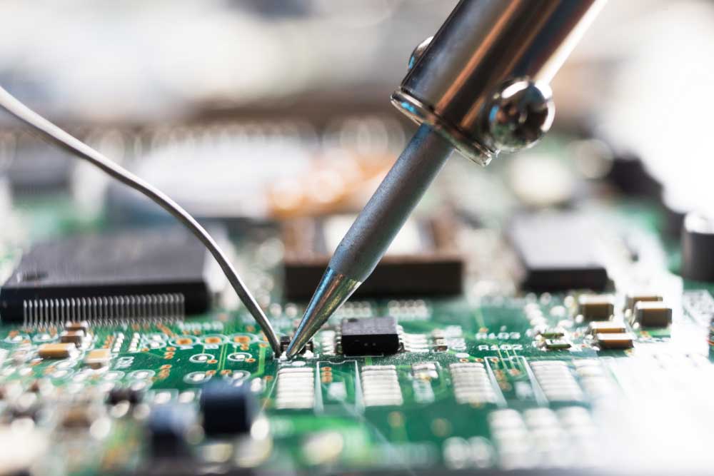
Repair and rework assembly is an essential process in PCB manufacturing and electronic assembly. It helps correct manufacturing defects, replace faulty components, repair damaged PCB traces, and improve overall product quality. Whether you’re working with SMT, through-hole, or BGA assemblies, repair and rework ensure printed circuit boards meet quality and performance standards. Below is a detailed guide explaining the repair and rework assembly process.
Repair and rework Assembly overview
Repair and rework assembly refers to the processes used to fix defects, correct errors, or modify a printed circuit board (PCB) or electronic assembly after it has been manufactured. This is common in electronics production, as it’s rare for every unit to be perfect, especially when dealing with complex circuits, high-density designs, or issues that arise during soldering and component placement.
Repair
The process of fixing a specific issue, such as a damaged trace, component, or connection, on an already assembled PCB. It may involve removing damaged parts, replacing them, or repairing traces or solder joints.
Rework
The act of correcting or modifying a PCB after it has been assembled but before it’s considered fully functional or finalized. Rework can involve things like adjusting solder joints, replacing components, or adding additional elements to correct an issue or improve performance.
Key Processes Involved in Repair and Rework Assembly
The repair and rework process can involve several different techniques depending on the nature of the problem and the type of assembly. Here are some of the primary methods used:
Visual Inspection
Objective: Identify defects like solder bridges, cold solder joints, missing components, or incorrect component placement.
Tools: Magnification tools (like microscopes), visual inspection systems (automated optical inspection, or AOI), and manual checklists.
Common Defects: Broken traces, incorrect component orientation, soldering issues, or component damage.
Desoldering
Objective: Remove faulty or unwanted components from the PCB.
Methods
Soldering Iron: Used to heat the solder joints and remove components by hand. This is the most common method for desoldering components like resistors, capacitors, or chips.
Desoldering Pump: A hand-held tool that uses suction to remove melted solder from joints.
Desoldering Braid: A woven copper braid that absorbs molten solder when heated with a soldering iron, leaving the joint clear.
Considerations: Care must be taken not to damage the PCB or surrounding components during desoldering.
Soldering (Rework)
Objective: Fix soldering problems like cold joints, insufficient solder, or bridges (short circuits).
Methods
Reflow Soldering: Involves using a reflow oven or a hot air rework station to melt solder paste and reflow it to form the correct joint. This is often used for surface-mount components (SMDs).
Hand Soldering: For smaller-scale fixes or through-hole components, a soldering iron is used to manually correct joints.
Hot Air Rework: Hot air is directed to a specific area to reflow solder paste and components, often used for SMD components that need to be replaced or repositioned.
Component Replacement
Objective: Remove defective components and replace them with new ones.
Process
Identify the defective component through testing or visual inspection.
Desolder the faulty component.
Solder a new component in place, making sure it is oriented and positioned correctly.
Special Consideration: Some components, especially those with sensitive leads or fine-pitch connections (like BGAs or fine-pitch QFNs), may require more precise handling using tools like soldering stations, reflow ovens, or hot air guns.
Repairing Broken Traces or Pads
Objective: Fix traces that are broken or pads that are lifted or damaged during manufacturing or testing.
Methods
Wire Jumpers: In cases where a trace is damaged, a jumper wire can be soldered to bypass the damaged area and re-establish the connection.
Conductive Ink: Special conductive ink or adhesive can be used to restore connections on the PCB, often in minor repairs.
Trace Rerouting: If a trace is broken and cannot be repaired with a jumper, the trace may be rerouted by cutting the PCB and applying a new route using conductive materials.
Correcting Component Orientation or Placement
Objective: Ensure that components are placed correctly, especially for polarized components like diodes, capacitors, and integrated circuits.
Methods
Repositioning Components: For misplaced components, the component is desoldered, and the correct placement is ensured before resoldering.
Component Marking: Components such as capacitors or diodes may need to be replaced in the correct orientation (positive and negative sides). If they are misoriented, rework is necessary to ensure proper polarity.
Cleaning
Objective: After repair or rework, cleaning ensures that no flux residues, solder balls, or other contaminants remain on the board.
Methods
Flux Removal: Cleaning solutions or brushes are used to remove flux residues.
Ultrasonic Cleaning: An ultrasonic bath can clean the entire board to remove small particles that are difficult to remove manually.
Air Blower/Brush: Used to remove excess solder or flux from the board after rework.
Testing and Validation
Objective: After the repair or rework is completed, the PCB must be tested to ensure that the problem has been fixed and that the board works as expected.
Methods
Visual Inspection: To ensure the repair work looks correct.
Functional Testing: To ensure the electrical performance is as expected, which may include checking voltage, current, and signal paths.
Automated Optical Inspection (AOI): A machine-based system that inspects the board after rework for missing or misaligned components and soldering defects.
In-circuit Testing (ICT): Checks the integrity of the board and individual components in a more thorough, automated fashion.
Common Repair and Rework Issues
Solder Bridges: Solder that has accidentally connected two adjacent pads, causing a short circuit. Fixed by desoldering and cleaning up the area.
Cold Solder Joints: Joints that are improperly soldered, often resulting in a poor electrical connection. These can be fixed by reflowing the solder or adding more solder to the joint.
Misplaced Components: Components placed in the wrong position or orientation. These are typically fixed by desoldering and repositioning the component.
Component Failure: A component that has failed due to heat, manufacturing defects, or electrical stress. The failed component is removed and replaced with a new one.
Damaged Pads/Traces: Traces that have been damaged or broken during assembly or testing. These are repaired using jumpers, conductive ink, or wire bonding.
Challenges in Repair and Rework
Delicate Components: Small components, particularly those with fine-pitch leads or BGAs (Ball Grid Arrays), require specialized equipment and expertise for rework.
PCB Damage: Repeated rework or excessive heat can damage the PCB material itself, potentially leading to delamination or trace damage.
Handling High-Density Boards: As PCBs become more complex with smaller components, the risk of damaging traces, pads, or components during rework increases.
Cost: Extensive repair and rework processes can significantly add to manufacturing costs, especially if the defect is widespread or difficult to address.
Tools Used in Repair and Rework Assembly
Soldering Irons & Soldering Stations: Used for adding and removing solder for component work.
Hot Air Rework Stations: Used for desoldering and soldering surface-mount components.
Desoldering Tools: Includes desoldering pumps, braid, and specialized vacuum tools.
Microscopes or Magnification Tools: Used for inspecting tiny components and connections.
Automated Optical Inspection (AOI) Systems: For detecting soldering defects, missing components, and other assembly issues.
Reflow Ovens: Used for large-scale reflow soldering but can also be used in rework when needed.
Multimeters/ICT Fixtures: Used for testing the electrical integrity of a repaired or reworked board.
Conclusion
Repair and rework assembly plays a critical role in ensuring the quality, reliability, and performance of printed circuit boards and electronic assemblies. From visual inspection and component replacement to PCB testing and validation, every step contributes to delivering high-quality PCB repair and rework services for modern electronic manufacturing.