

System Integration and Box Build Assembly Process
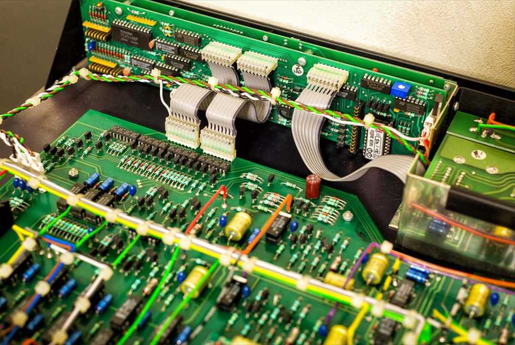
System Integration and Box Build Assembly refers to the process of assembling and integrating complex electronic systems within a protective enclosure or box. This includes not only assembling the electronic components onto a printed circuit board (PCB), but also incorporating those PCBs into a larger system, connecting various subsystems (such as power supplies, connectors, sensors, switches, displays, etc.), and ensuring the final product is properly housed in a box or enclosure for protection, usability, and functionality.
Box build assembly typically involves the integration of hardware, software, and mechanical elements, creating a fully functional system or product. This process is crucial for industries like consumer electronics, automotive, industrial equipment, medical devices, telecommunications, and aerospace, where end products are often complex systems that require both electronic and mechanical assembly.
Key Steps in System Integration Box Build Assembly
The system integration and box build assembly process generally includes several stages: Design and Engineering, Assembly of the Electronics, Mechanical Assembly, System Integration, Testing and Quality Assurance, and Final Packaging. Below is a detailed breakdown of each stage:
Design and Engineering
The first step in the box build process is to design the overall system architecture, including both the electronics and the mechanical aspects.
System Design and Requirements
- The design team defines the functional requirements for the system, which includes the integration of various components such as:
- PCBs (Printed Circuit Boards)
- Power Supplies
- Connectors
- Cables and Wires
- Sensors, Switches, and Buttons
- Displays (LCD, LED, etc.)
- The system’s size, shape, and layout will be determined by how the electronics and mechanical components fit together in the final enclosure.
Prototyping and Mechanical Design
- Mechanical engineers design the enclosure or box that will house the system. The enclosure is typically made from metal (aluminum, steel) or plastic, depending on the application.
- Thermal management, ventilation, accessibility, and ergonomics are important design considerations to ensure the system operates reliably.
- CAD software is used to design the enclosure, including features such as cut-outs for connectors, mounting points, and access panels.
- Electrical Design and Integration
- The electrical engineers focus on the circuit design, selecting and designing the PCBs, power distribution, wiring, and connectors.
- Ensuring the PCB design can interface properly with other system components (e.g., sensors, actuators) is critical.
Assembly of the Electronics
Once the design is complete, the assembly of the electronic components begins. This step typically includes the SMT (Surface-Mount Technology) assembly of the PCB, followed by the integration of the PCB with the other system components.
PCB Assembly (SMT and Through-Hole Components)
- The PCB may undergo SMT (Surface-Mount Technology) or through-hole assembly, depending on the type of components and the complexity of the design.
- After the PCB is assembled, it is tested to ensure functionality before being integrated into the overall system.
Component Sourcing and Procurement
- The Bill of Materials (BOM) is finalized to procure all necessary components for the assembly. This includes resistors, capacitors, ICs, connectors, and any special components that may be required for the system.
Cable Assembly
- Wiring harnesses and cable assemblies are created for power distribution and signal connections. This involves cutting, stripping, and crimping wires, and attaching connectors that will interface with the PCB or other components.
Mechanical Assembly
This phase involves the assembly of the mechanical parts of the system, including the enclosure and any external components. This is often done in parallel with the electronic assembly.
- Enclosure Preparation
- The designed enclosure is sourced and modified if necessary. It may require:
- Cutting or drilling holes for connectors, switches, and displays.
- Mounting brackets or rails for securing the PCB or other internal components.
- Thermal management solutions such as heat sinks, fans, or ventilation holes are also incorporated to keep the system within safe operating temperatures.
Mounting the Electronics Inside the Box
- The PCB, power supply, and other electronic modules are mounted inside the enclosure. This may involve securing them with screws, clips, or brackets, and connecting them using cables, wires, or connectors.
- Cable management is important to ensure that wires are neatly routed and don’t interfere with airflow or operation.
Mechanical Subsystems Integration
- Other mechanical subsystems, such as buttons, switches, dials, displays, keypads, or LED indicators, are integrated into the box as per the design.
- This step may also include testing of moving parts, such as motors or actuators, to ensure they function properly within the system.
System Integration
This is the phase where all parts of the system come together. It involves both the electrical integration and the mechanical integration of the components.
- Connecting Components
- Wiring and interconnections between the PCB, power supply, displays, connectors, and mechanical components are completed. This includes:
- Power cables for powering the system.
- Data cables for communication between subsystems (e.g., USB, serial, Ethernet).
- Signal cables for connecting sensors, actuators, and other I/O devices.
Firmware or Software Integration
If the system includes programmable components (e.g., microcontrollers, FPGAs), the firmware or software is loaded onto the devices, and the system is configured for its intended operation.
Pre-Testing
- Once all components are connected, preliminary testing is done to check the system’s functionality. This could involve:
- Power-up testing to check for electrical shorts or wiring issues.
- Basic functional testing of individual components to ensure they are working before more extensive system testing.
Testing and Quality Assurance
Comprehensive testing is crucial to ensure the system operates as intended. Testing verifies both the electrical performance of the system and its mechanical integrity.
Electrical Testing
- This includes in-circuit testing (ICT) and functional testing to ensure that all electrical connections are correct and that the system works as expected.
- Power-on testing verifies that the system powers up correctly and that all components are functioning within specifications.
Functional Testing
- The system is tested in real-world conditions to ensure it meets its design specifications. For example:
- Signal integrity tests for communication protocols (e.g., Ethernet, USB).
- Environmental tests to check for temperature extremes, humidity, or vibration resistance.
- Performance testing to verify that the system performs its intended tasks.
Mechanical Testing
- The enclosure is checked for proper fit, durability, and functionality.
- Stress testing is conducted to check if the system can withstand physical impacts, excessive heat, or vibration during transport or normal use.
Compliance Testing
The system may need to meet specific industry standards or regulatory requirements, such as CE, UL, or RoHS certifications, depending on the product type and target market.
Final Packaging
Once the system has passed all tests and quality checks, it is ready for final packaging.
- Packing the System
- The system is carefully packed in anti-static bags or foam inserts to prevent damage during shipping. The packaging must be designed to prevent physical damage and minimize electrostatic discharge (ESD).
Documentation and Labels
- Documentation, such as user manuals, installation guides, and safety instructions, is included with the system.
- Proper labels with product information, serial numbers, and safety certifications are affixed to the box or system.
Applications of System Integration Box Build Assembly
System integration box build assemblies are used in a wide variety of industries and applications, including:
- Consumer Electronics: Smart home devices, entertainment systems, gaming consoles, etc.
- Automotive: ECU (Electronic Control Units) assemblies, infotainment systems, sensors, and controllers.
- Medical Devices: Diagnostic machines, patient monitors, infusion pumps, and wearable devices.
- Industrial Equipment: Control panels, PLCs (Programmable Logic Controllers), robotics, and automation systems.
- Telecommunications: Networking equipment, routers, and switches.
- Aerospace: Flight control systems, avionics, satellite communication equipment.