

What is a Single-Sided PCB? A Comprehensive Guide
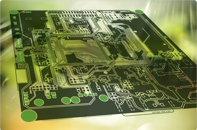
In the rapidly evolving world of electronics, it is easy to get caught up in the hype of ultra-dense, multi-layered Printed Circuit Boards (PCBs) that power our smartphones, advanced computers, and aerospace technology. However, the foundation of the electronics industry relies heavily on a simpler, incredibly reliable, and cost-effective solution: the single-sided PCB.
Whether you are a seasoned hardware engineer, a procurement manager, or an electronics enthusiast, understanding the intricacies of single-sided PCBs is crucial. At Altest Corp, we believe that choosing the right board for your project is the first step toward product success. In this comprehensive guide, we will dive deep into what single-sided PCBs are, the materials used to build them, their manufacturing process, design considerations, and why they might be the perfect fit for your next project.
1. What is a Single-Sided PCB?
A single-sided PCB, also known as a single-layer PCB, is the most basic and common type of printed circuit board. As the name suggests, it consists of a single layer of conductive material (usually copper) laminated onto one side of an insulating substrate (the non-conductive base).
Because the conductive copper layer is only present on one side, all the electronic components and the conductive traces that connect them are constrained to their respective sides. Traditionally, in a through-hole design, the components are placed on the non-copper side (the “component side”), and their leads are passed through holes to be soldered onto the copper pads on the opposite side (the “solder side”). With Surface Mount Technology (SMT), both the components and the copper traces reside on the exact same side.
Despite their simplicity, single-sided boards are the workhorses of the electronics industry, offering unparalleled efficiency for straightforward circuitry.
The Anatomy of a Single-Sided PCB
To fully grasp how a single-sided board functions, we must look at its cross-sectional anatomy. A standard single-sided PCB is composed of four primary layers:
The Substrate (Base Layer): This is the core material of the PCB, providing structural rigidity and electrical insulation.
The Conductive Layer (Copper): A thin sheet of copper foil is laminated onto one side of the substrate. This layer is etched to create the pathways (traces) that allow electricity to flow between components.
The Solder Mask: Applied over the copper layer, this polymer layer protects the copper from environmental damage (like oxidation) and prevents accidental solder bridges from forming between closely spaced traces during assembly. It is what gives PCBs their iconic green color, though other colors are available.
The Silkscreen: Printed on top of the solder mask (and often on the component side), the silkscreen adds human-readable letters, numbers, and symbols to the board. It indicates component placement, polarity, and test points, making assembly and troubleshooting much easier.
2. Materials Used in Single-Sided PCBs
The performance, durability, and cost of a single-sided PCB are heavily dictated by the materials used, particularly the substrate. Because single-sided boards are often chosen for cost-sensitive or specialized applications, the material choices vary widely.
Common Substrate Materials
FR-4 (Flame Retardant 4): The industry standard. FR-4 is a woven fiberglass cloth with an epoxy resin binder. It offers excellent mechanical strength, moisture resistance, and electrical insulation. While more expensive than paper-based substrates, it provides superior durability.
FR-1 and FR-2: These are paper-based substrates impregnated with phenolic resin. They are highly cost-effective and easy to punch or shear, making them ideal for high-volume, low-cost consumer electronics. However, they lack the mechanical robustness and heat resistance of FR-4.
CEM-1 (Composite Epoxy Material 1): CEM-1 combines a paper core with woven fiberglass surfaces, impregnated with epoxy resin. It acts as a middle ground between FR-2 and FR-4, offering better mechanical properties than paper boards while remaining cheaper than full fiberglass (FR-4). It is incredibly popular for single-sided boards.
Aluminum/Metal Core (MCPCB): In applications that generate significant heat (such as high-power LED lighting or power supplies), an aluminum base is used. The metal core acts as a highly efficient heat sink, drawing thermal energy away from sensitive components.
Copper Weights: The thickness of the copper layer is measured in ounces (oz) per square foot. Standard single-sided boards use 1 oz copper (approximately 35 micrometers thick). However, for applications involving higher electrical currents, such as power converters or motor controllers, heavier copper weights (2 oz, 3 oz, or even higher) can be utilized to prevent the traces from overheating and failing.
3. Advantages of Single-Sided PCBs
Why do manufacturers continue to produce billions of single-sided PCBs every year when multi-layer technology is readily available? The answer lies in the distinct advantages this architecture provides.
Cost-Effectiveness
The most significant advantage of a single-sided PCB is its low manufacturing cost. Because there is only one layer of copper to etch, no complex through-hole plating required, and fewer overall lamination steps, the material and processing costs are drastically reduced. For consumer goods with tight profit margins, this cost saving is vital.
High-Volume Manufacturing Efficiency
Single-sided boards are incredibly easy to manufacture at scale. The straightforward production process means that fabricators can churn out thousands or millions of units in a fraction of the time it takes to produce multi-layer boards.
Faster Lead Times
Fewer manufacturing steps equate to faster turnaround times. If you are in the rapid prototyping phase of a simple circuit or need an urgent production run to meet market demand, single-sided PCBs can be fabricated and delivered much faster than their multi-layer counterparts.
Simplicity in Design and Troubleshooting
From a layout perspective, routing a single-sided board is a straightforward exercise (though it can be an enjoyable puzzle to solve without using vias). This simplicity extends to testing and troubleshooting. If a board fails in the field, technicians can easily trace the single layer of circuitry to identify shorts, opens, or failed components without needing to X-ray the board to see internal layers.
Unmatched Reliability for Simple Circuits
Fewer variables mean fewer points of failure. Because single-sided boards do not rely on plated through-holes (vias) to connect different layers—a common point of mechanical failure in multi-layer boards subjected to thermal cycling—they are exceptionally reliable for the circuits they host.
4. Disadvantages and Limitations
While highly beneficial, single-sided PCBs are not suitable for every application. It is important to understand their limitations to determine if they fit your specific design parameters.
Routing Constraints
The biggest challenge when designing a single-sided board is the lack of routing space. Because all traces must exist on a single plane, they cannot cross over one another without creating an electrical short. If a trace needs to get to the other side of the board and its path is blocked, the designer must use a “jumper” wire (a zero-ohm resistor or a physical wire) to jump over the obstacle. This can complicate assembly if overused.
Lower Component Density
Due to the routing constraints mentioned above, components must be spaced further apart to allow room for the traces to snake around them. Consequently, you cannot achieve the ultra-high component density required for modern smartphones, laptops, or advanced IoT devices using a single-layer board.
Poor High-Speed and RF Performance
Single-sided boards are generally unsuitable for high-speed digital circuits, radio frequency (RF) applications, or complex analog designs. They lack an internal ground plane, which is essential for controlling trace impedance, managing electromagnetic interference (EMI), and preventing signal crosstalk.
5. Common Applications of Single-Sided PCBs
Given their balance of cost and performance, single-sided PCBs are ubiquitous. They are found in almost every room of your house and in countless industrial applications.
Power Supplies and Converters: Many switch-mode power supplies, AC adapters, and battery chargers rely on single-sided boards, often utilizing heavier copper for current handling.
LED Lighting: The lighting industry heavily utilizes single-sided Aluminum-backed PCBs to manage the heat generated by high-power LEDs in automotive headlights, streetlights, and home lighting fixtures.
Consumer Electronics: Household appliances like coffee makers, washing machines, microwaves, and calculators typically use single-sided CEM-1 or FR-2 boards for their basic control logic.
Automotive Dashboards: While modern car infotainment systems use complex boards, many basic dashboard indicators and lighting arrays still rely on single-sided technology.
Relays and Sensor Modules: Basic industrial control circuits, photoelectric sensors, and simple relay boards benefit from the high reliability and low cost of single-layer construction.
6. Design Considerations for Single-Sided PCBs
Designing for a single layer requires a different mindset than designing a multi-layer board. Here are some best practices our engineering team at Altest Corp recommends:
Strategic Component Placement
In single-sided design, component placement dictates the success of your routing. Group functionally related components closely together. Place larger, multi-pin components (like microcontrollers or large connectors) first, and orient them to minimize crossing paths.
Utilizing Jumpers (Zero-Ohm Resistors)
When traces absolutely must cross, you will need to use jumpers. However, try to minimize their use. Every jumper is an extra component that must be sourced, placed, and soldered, which incrementally adds to the assembly time and cost.
Maximizing Trace Widths and Clearances
Since space on a single-sided board isn’t shared with internal vias, try to use the widest traces possible, especially for power and ground rails. This reduces resistance and thermal buildup. Additionally, leave ample clearance between traces to reduce the risk of solder bridging during the wave soldering process.
Pad Sizes
Because single-sided boards lack the mechanical reinforcement of a plated-through hole (where copper coats the inside of the hole barrel), the component’s mechanical stability relies entirely on the surface area of the copper pad on the bottom side. Therefore, it is standard practice to use larger, more robust pads (often teardrop-shaped) on single-sided boards to prevent the pads from tearing off the substrate under mechanical stress.
7. The Single-Sided PCB Manufacturing Process
Understanding how these boards are made can help you design them more effectively. Here is a high-level overview of the standard manufacturing process:
Material Preparation: The process begins with a large sheet of the chosen substrate, pre-laminated with copper on one side. The panel is cut to the appropriate size.
Drilling: The panel is placed into a CNC drilling machine. Holes for through-hole components and mechanical mounting are drilled. Unlike multi-layer boards, these holes are left bare and are not plated with copper.
Image Transfer (Photolithography): The panel is cleaned and coated with a light-sensitive film called photoresist. The PCB design (the artwork) is printed onto a transparent film. This film is aligned over the board and exposed to UV light. The light hardens the photoresist over the areas where copper traces should remain.
Etching: The unhardened photoresist is washed away, exposing the unwanted copper. The board is then submerged in a chemical etching solution (usually ferric chloride or alkaline etchant), which dissolves the exposed copper, leaving only the copper protected by the hardened photoresist—your circuit traces.
Solder Mask Application: The board is coated with solder mask ink. Another UV exposure process hardens the mask everywhere except over the copper pads where components will be soldered. The unhardened mask is chemically washed away.
Surface Finish: To prevent the exposed copper pads from oxidizing and to ensure excellent solderability during assembly, a surface finish is applied. Common finishes for single-sided boards include HASL (Hot Air Solder Leveling) or OSP (Organic Solderability Preservative).
Silkscreen Printing: An inkjet printer or traditional screen-printing method applies the component designators and logos onto the board.
Routing and V-Scoring: The individual PCBs are cut out of the larger manufacturing panel using a CNC router, or they are V-scored (a shallow groove is cut into the board, allowing them to be snapped apart later).
Electrical Testing: The final step is rigorous testing. Flying probe testers or bed-of-nails fixtures check the board for continuity (ensuring traces are connected) and isolation (ensuring traces aren’t shorted together).
8. Single-Sided vs. Double-Sided vs. Multi-Layer PCBs
To put single-sided boards in context, here is a brief comparison with other PCB architectures:
Single-Sided: Conductive copper on one side. Lowest cost, easiest to manufacture, ideal for low-density, high-volume consumer goods.
Double-Sided: Conductive copper on both the top and bottom sides, connected by plated through-holes (vias). Allows for intersecting traces and higher component density without utilizing jumpers. Moderately priced.
Multi-Layer (4+ layers): Multiple layers of copper separated by insulating substrates and connected by complex via structures (blind, buried, and through-hole). Essential for high-speed routing, impedance control, and ultra-high component density (smartphones, motherboards). Highest cost and longest manufacturing time.
9. Why Choose Altest Corp for Your PCB Needs?
At Altest Corp, we understand that whether you need a simple single-sided CEM-1 board for a household appliance or a highly complex multi-layer board for aerospace applications, quality is non-negotiable.
As a leading Electronics Manufacturing Services (EMS) provider, we don’t just build boards; we provide end-to-end solutions. When you partner with Altest, you benefit from:
Design for Manufacturability (DFM) Checks: Our engineering team reviews your single-sided designs to ensure they are optimized for cost-effective fabrication and assembly, catching potential routing or pad-size issues before they hit the factory floor.
Material Flexibility: We source only the highest quality substrates, from standard FR-4 to specialized aluminum cores for your thermal management needs.
Turnkey Assembly: We handle both the bare board fabrication and the final component assembly, whether you are using traditional through-hole techniques or surface mount technology.
Rigorous Quality Control: Every board that leaves our facility is subjected to stringent testing protocols to ensure 100% functionality and reliability.
Conclusion
Single-sided PCBs may not make the headlines in technology magazines, but they are the undisputed backbone of everyday electronics. Their simplicity is their greatest strength, offering unmatched cost-efficiency, rapid production times, and robust reliability for low-density circuits.
By understanding their material properties, design constraints, and manufacturing processes, you can make informed decisions that drastically reduce your product’s time-to-market and production costs.
Ready to bring your next electronic project to life? Contact the engineering experts at Altest Corp today to discuss your PCB fabrication and assembly needs. We are here to help you build better, faster, and smarter.